MECHANICAL CAD
Computer Aided Design (CAD)is the use of computer systems to assist in the
creation, modification, analysis, or optimization of a design. CAD software is used
to increase the productivity of the designer, improve the quality of design, improve
communications through documentation, and to create a database for manufacturing.
CAD output is often in the form of electronic files for print, machining, or other
manufacturing operations
The most basic role of CAD is to define the geometry of design – a mechanical part,
a product assembly, an architectural structure, an electronic circuit, a building
layout, etc. The greatest benefits of CAD systems are that they can save considerable
time and reduce errors caused by otherwise having to redefine the geometry of the
design from scratch every time it is needed.
PART DESIGN
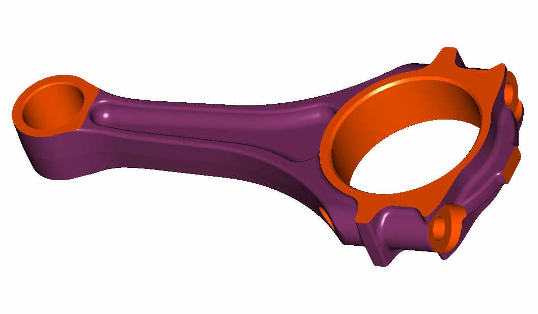
The part design work bench/mode is a parametric and feature-based environment in
which you create solid models. The basic requirement for creating a solid model
is a sketch.
The tools in the part design workbench can be used to convert the sketch into a
feature. This workbench also provides other tools to apply the placed features,
such as fillets, chamfers, and so on. These features are called the dress-up features.
You can assign materials to the model in this workbench.

ASSEMBLY DESIGN
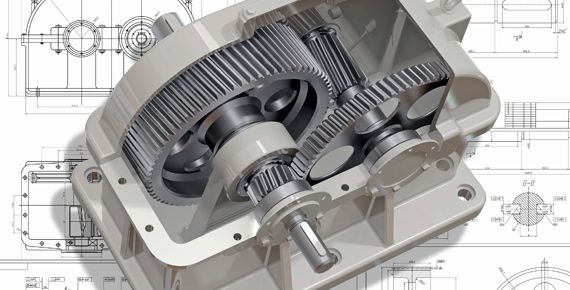
The components are brought together and assembled in the Assembly Design workbench
by applying suitable parametric assembly constraints to them.
The assembly constraints allow you to restrict the degrees of freedom of the components
at their respective work positions.

DRAFTING
After creating parts and assembling them, you need to generate their drawing views.
A 2D drawing is the life line of all the manufacturing systems because on the shop
floor or tool room, a machinist mostly needs the 2D drawings for manufacturing.
The Drafting workbench is a specialized environment for generating drawing views,
modify, and apply dimensions and annotations to them.
The parametric dimensions added to the component in the part design workbench during
its creation can also be generated and displayed automatically in the drawing views.
The generative drafting is bidirectionally associative in nature. You can also generate
the Bill of Material (BOM) and balloons in the drawing views.

SHEET METAL DESIGN
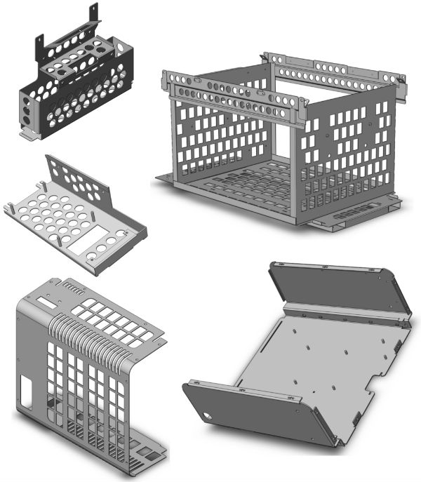
The Sheet metal Design workbench/mode is used for the designing the sheet metal
components. Generally, the solid models of the sheet metal components are created
to generate the flat pattern of the sheet, study the design of the dies and punches,
study the process plan for designing, and the tools needed for manufacturing the
sheet metal components.
The component that has a thickness greater than zero and less than 12 mm is called
a sheet metal component. It is easy to create components by using manufacturing
processes such as bending, stamping, and so on. It is not possible to machine such
a thin component. After creating a sheet metal component, you need to flatten it
in order to find the strip layout. Based on the layout detail, you can design punch
and die.

SURFACE DESIGN
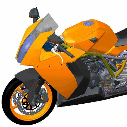
The product and industrial designers give special importance to product styling
and providing a unique shape to components. Generally, this is done to make the
product look attractive and presentable. Most of the times, the product’s shape
is managed using the surface modeling techniques. Surface models are three-dimensional
models with no thickness and do not have mass properties.
The Surface Design workbench is also a parametric and feature-based environment,
and is used to create wireframe or surface models. The tools in this workbench are
similar to those in the Part Design workbench with the only difference that the
tools in this environment are used to create basic and advanced surfaces.